
How to design spur gear is something that must be mastered by mechanical engineer. If you go to college and you take a major in mechanical engineering so you will get design gear courses, one of the gear that you can design is spur gear. If you want to design spur gear, you must know formula of spur gear, such as N = P/M (N : Number of teeth, P : Diameter Pitch, M : Modul). This solidworks tutorial, Tutorial of CAD will show you how to design spur gear in solidworks 2019.
How to Create Spur Gear in Solidworks 2019 – Solidworks Tutorial
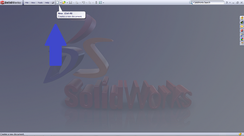
– First step is you need to create new drawing to begin draw in solidworks. Click New and choose part menu.
– Or you can go to Tool Box menu directly to begin create spur gear in solidworks.
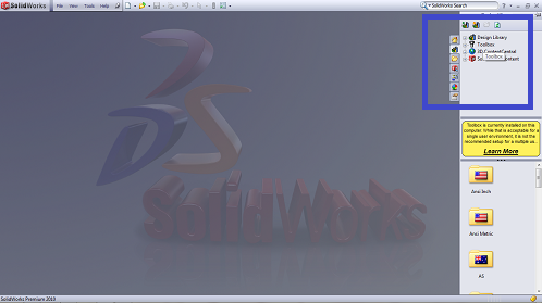
– After that you can choose one of standard that you want to choose. you can use ANSI (American National Standards Institute) Metric or ANSI Inch or ISO (International Standards Organisation) or other standard that you want to choose. Usually in each country they have their own standards.
– But in this solidworks tutorial, I will use ANSI Metric. Click the standard and choose Power transmission menu – click Gear – click Spur Gear – and right click and choose Create Part and wait a second until you see the gear and parameter choice.
–
More from my site
 Design Spur Gear in Solidworks Manually – Solidworks Tutorial
 Let’s Design Control Arm With Solidworks – Solidworks Tutorial
 The Tutorial of Drawing Rod Cover with SolidWorks – Solidworks Tutorial
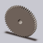 How to Make Spur Gear With SolidWorks – Solidworks Tutorial
 How to Make Rod Cover by SolidWorks – Solidworks Tutorial
 The Introduction of Solidworks – Solidworks Tutorial Basic


[…] of CAD will show you how to create spur gear in autodesk inventor, before we showed you how to create spur gear in solidworks. Let’s follow me to know how to create it in this inventor […]