
Hi design engineer, welcome back with me Tutorial of CAD that will show you about design with AutoCAD, Autodesk Inventor, Catia, SolidWorks. But this time I will give you autoCAD tutorial, and the title is how to design control arm with autocad. This part is one of part of machine that you may know it. I think this part is so simple to design with autocad or other CAD software, especially if you use special design software for 3D (3 Dimension). If you are accustomed to drawing with Autocad, I think it will also be easy to make this design.
Design Control Arm With AutoCAD – AutoCAD Tutorial
– First, Open AutoCad Software. And then click FILE menu – click New to make new window.
– Click Line menu or you can type L in command column and then click enter. Click in drawing area or you can type 0,0 in command and enter to get central coordinate. After that type @100,0 to make line 100 mm in X coordinate. 
– Next step is making circle at beginning of the line and end of the line. Make circle in the beginning with radius 30 mm and 15 mm. Click Circle menu or you can type C and then enter, click beginning of line and type R enter and type again 30 then enter. Click circle again or type C and enter, click the beginning of line for center of circle, type R enter and type 15 enter. If you are correct to follow my instruction, your draw will be like below :
– Next, make circle again with radius 50 mm and 40 mm. Type C and enter, click the end of line to make it center of the circle, and type 50 enter. Make circle again, type C enter or click Circle menu and click the end of line to be center of circle, type 40 enter. check below :

– Continue to next step, make Line again with length 125 mm and 51 degrees, click Line menu or type L enter. Click the end of first line and then type @125<51 Enter. Check below :
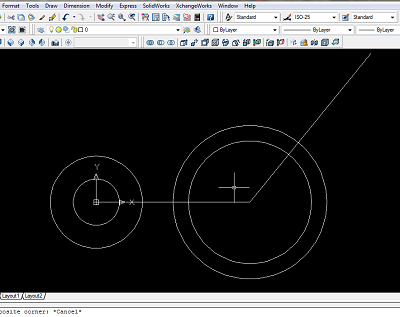
– Make circle again in the end of angle line with radius 25mm and radius 10mm. Click Circle menu in the bar or type C enter, type R enter and 25 enter. And then make circle with 10mm also.

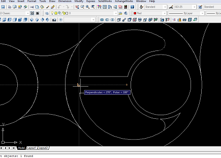
– And now please make arc line to join first big circle with radius 40 mm. To make it easier, you can make a circle first with a radius 40 mm. check below:

Next of Design Control Arm With AutoCAD – AutoCAD Tutorial
– Move the circle that you just made until you join between 2 big circle. If you are confused, check picture below. Click Move menu or type M enter, select object or select the circle that you want to move.
 – After that cut or trim the circle until like below. Click Trim menu or type TR enter type ALL enter 2 times and choose the line that you want to trim, after you trim the line click enter.
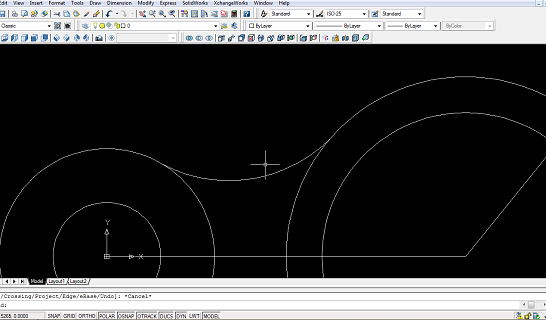
– After you mirror the arc line. Click Mirror menu or type MI enter, select object or select line that you want to mirror then enter. Then click first point and second point that will be a mirror (select beginning of axis line and the end of axis line). After that you will see choices, it is N / Y. N = NO, it means no erase the line / part of mirror. Y = Yes, it means you will erase the line or part of mirror. And you choose N and then enter.
– Next, we will make arc line again, it’s same like above. Make circle again with radius 60 mm, and move until you can join the Big circle. Click C enter and then click the center of circle and type 60 enter. Check below :

– Then click Move or type M enter, select the circle enter, click area drawing around big circle and move the circle until the circle touch the big circle.
– Click Trim menu or type TR enter, type ALL enter 2 times then select the line that you want to trim or cut. Check below to know the result:

– After that you Mirror again the arc line, Type MI enter select the arc line enter, select first point and second point and then enter (select point of axis line).

– Click Line menu or type L enter, then make line to join the arc line. Check picture below:

Next of Design Control Arm With AutoCAD – AutoCAD Tutorial
– Click Region menu or type REG enter cos we will join arc and line. Select arc and the line (4 object) then enter. And click Region menu again to join other arc and line (4 object). Check below:

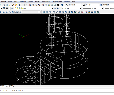
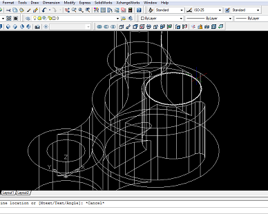
– Click SW Isometric menu. Click Extrude menu or type EXT enter then select all of circle except circle radius 40 mm, then give the high size 25 mm and then enter.
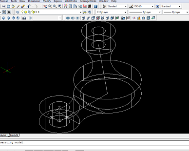
– Make line to help you copy all of extrude circle. Click Line menu or Type L enter then click center point of big circle and type @0,0,25 enter. check below:

– Next we want to copy all of extrude circle. Type CP enter then select all of extrude circle (5 object) and enter. Click end point that will be first point of copy.

– After that click perpendicular that will be end point of copy then enter.
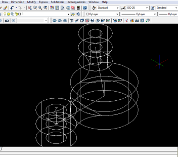
– Erase line that we have made, click Erase menu or type E enter then select the line then enter.
– Next, we want to extrude again. Click extrude menu or type EXT enter, select 2 arc line (2 object) enter, give the size 20 mm then enter. Click conceptual visual style (visual style bar menu) menu to see 3D.
Continue to Design Control Arm With AutoCAD – AutoCAD Tutorial
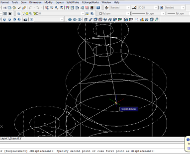
– Click 2D Wireframe again to see 2D. Next we will copy the arc extrude, but before copy we make line first, click line menu or type L enter, click center point of big circle and type @0,0,20 then enter.
– Type CP enter, select arc extrude (2 object) enter, click end point to be first point of copy and then click second point of copy / center point then enter. after that you can see 3D with click conceptual visual style.

– Click 2D wireframe to see 2D and erase the line that have helped you to copy.
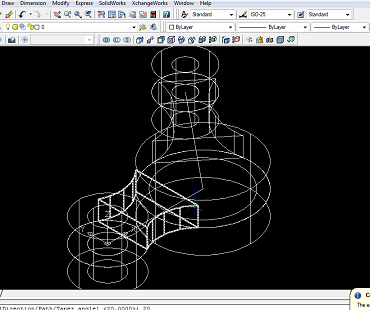
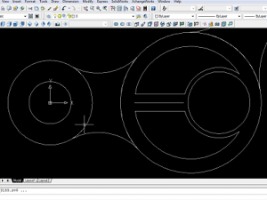
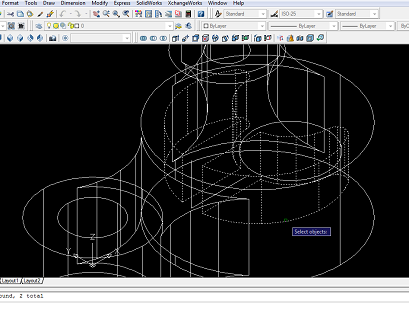
– Next step, you have to join all of extrude part (10 object) except circle extrude radius 15 and radius 10 (4 object). Click Union menu or type UNI enter, select all of object (10 object) and then enter. You can see 3D visual.
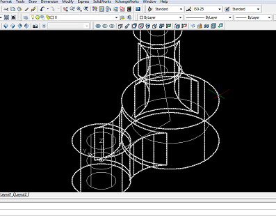
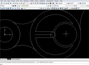
– Next step, we will make hole in the circle extrude using Subtract menu. To make it easier, active 2D wireframe first. Then click Subtract menu, click main part then enter.

– Then click all of small circle extrude then enter. To more clearly you can active conceptual visual style 3D.

– Click 2D wireframe and then top view. Make line again to help us make circle radius 22 mm and 25 mm. Click Line menu or type L enter, click center of big circle, type @20,0 enter.

– Then make circle with radius 22 mm and 25 mm. Click Circle menu or type C enter click end point of the line that we have just made, type 22 enter. Then make circle 25 mm. Then erase center line that connect center of circle (100 mm, 125 mm).

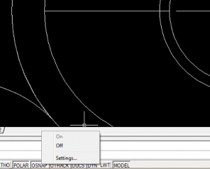
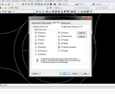
– Make Line again that connect quadrant circle radius 22 mm with quadrant circle 40 mm. (if your quadrant not active, you can active first. Right click in OSNAP below drawing area, then click setting and then check quadrant).
Continue to Design Control Arm With AutoCAD – AutoCAD Tutorial
– Then click Line menu, click quadrant of circle radius 22 mm then click quadrant of circle radius 40 mm.

– After that we will use Offset menu to make line easier with size 6 mm. Click Offset menu or type O enter, type 6 enter, select the line that want to offset, click top of line and click again the line then click bottom of the line and then enter.

– After that you cut all of line that not be used. Click Trim menu or type TR enter type ALL enter 2 times, and select line or arc. Erase line that are not used. See the result below:
– Make circle radius 5 mm to make arc in angle. Click circle menu or type C enter, click the end of center line or beginning center line (so that it’s same axis with the arc line), and type 5 enter.
– Move the small circle radius 5 mm until like picture below. Click Move menu or type M enter, click area drawing and move the circle like below: ( if you are difficult to move the circle, non active the OSNAP and POLAR first)

– Click trim menu or type TR enter type all enter 2 times, and trim the angle line and the circle, so that it becomes as shown below:

– Mirror the arc using line offset to be line mirror. Click Mirror menu or type MI enter, select object.

– And then move mouse cursor to mirror line then enter.

– Click first point in the beginning line and second point in the end of line, then enter.

– Trim the line, type TR enter, type ALL enter 2 times, select the line and enter. See the result like below:

Design Control Arm With AutoCAD – AutoCAD Tutorial
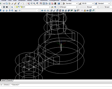
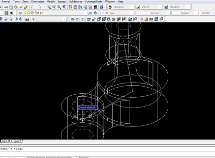
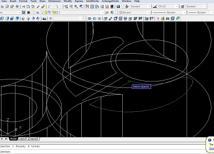
– Active or click SW isometric cos after this we want to extrude circle and arc object. But before it, you have to region the line to join all the line. Click Region menu or type REG enter, select all of object (4 object) then enter.

– Then region other line and arc.
– Next, extrude all of object 2D with extrude size 25 mm. Click extrude menu or type EXT enter, select object (2 object except the circle) enter, type 25 enter. You can check with conceptual visual style menu.

– Active 2D wireframe again and then make line to help you copy the extruded object. Type L enter, click end point of line mirror and type @0,0,25 enter 2 times.


– Next, you copy the extruded that you have just extruded. Type CP enter, select object (2 object) enter, click end of line (Top point) that have just made for first point and then click beginning of line for second point (bottom point), then enter.

– After that, you union the extruded (top and bottom). Click Union menu or type UNI enter, select the object and enter (2 object). And then union again for other object, so that you see the result like below:

– Next we want to the object extruded. Click Subtract menu and then select main part enter.

– Select subtract part (arc extruded) then enter. Then you can see the result with active the Conceptual Visual Style menu.


– Subtract other object (other arc extrude).

Continue to Design Control Arm With AutoCAD – AutoCAD Tutorial
– Click 2D wireframe, move circle radius 22 mm. Type M enter, click center of circle, then type @0,0,25 enter.
– Select top view, Make line to help you can get center for circle. Type L enter, click center point and then quadrant point or perpendicular point then enter.

– Make circle with radius 4 mm. Click circle menu or type C enter, click midpoint of line, type 4 enter.

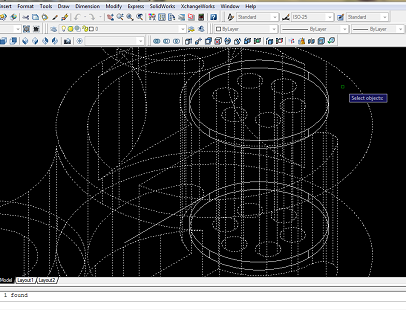
– Now we want to copy the circle with Polar Array menu. Click array menu, select polar array, select object, see picture below:
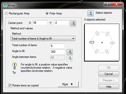
– Then choose the circle and enter.

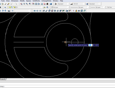
– Pick center point, and click center point of big circle.

– Fill total number of items is 6, Angle = 360, and click OK, see the result.

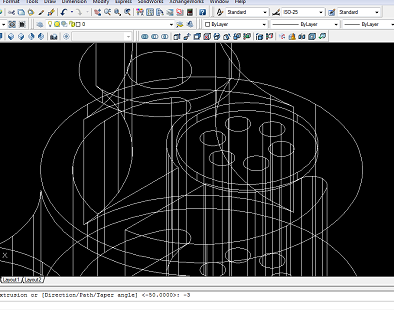
– Click SW isometric to see 3D. Now, extrude all of circle that have just made. Type EXT enter, select object (6 object) enter, type -50 enter (cos the extrude will go to bottom).

– Next, Subtract all of extruded circle, cos we want to make hole there. Click subtract menu, select main part then enter,

– Select all of circle radius 4 mm then enter. Active conceptual visual style to see 3D.


– Active 2D wireframe again, Extrude the circle radius 22 mm. Type EXT enter, select the circle and enter, type 3 enter.
– Copy the extruded circle to bottom. Type CP enter, Click top center of extrude circle,

– Type @0,0,-47 then enter, see the result:

Next of Design Control Arm With AutoCAD – AutoCAD Tutorial
– Subtract extruded circle. Click subtract menu, select main object then enter,
– Select the extruded circle (2 object) then enter.


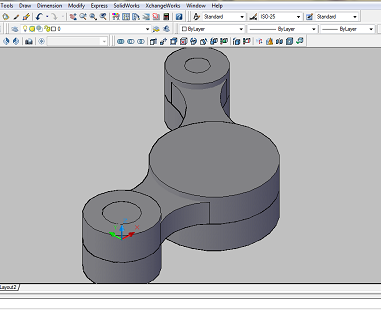
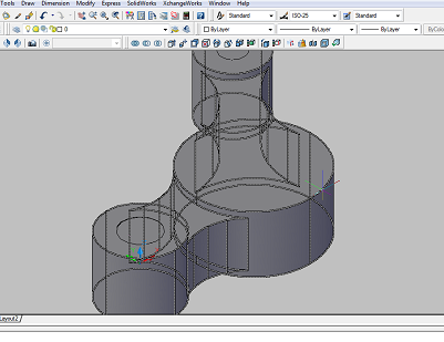
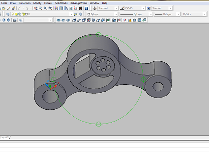
– You can use FREE ORBIT menu to see the bottom.
– For finishing, you can chamfer the angle of part with 0.5 mm. Click chamfer menu, select object/area,

– Choose next, cos you just need top area to be chamfered,

– Click OK, type first distance of chamfer is 0.3 then second distance is 0.3, click the angle that you want to chamfer (2 object) and enter.

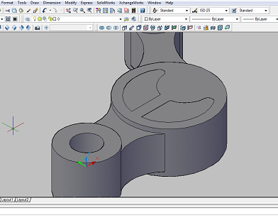
– Do chamfer to all of angle that you think it have to be chamfered. See the Video Tutorial of How to Design Control Arm With AutoCAD below and don’t forget to like and subscribe my youtube, and also follow my fanspage. Thanks for coming in my blog.
More from my site
 How to Create Pipe Using Sweep Feature Command – AutoCad Tutorial
 How to Extrude Path in AutoCAD – AutoCAD Tutorial
 How to Make Bracket by Autocad – AutoCAD Tutorial
 How to Use Revolve Menu on AutoCAD – AutoCAD Tutorial
 The Introduction of Autocad – AutoCAD Tutorial Basic
 How to Create Spur Gear in Solidworks 2019 – Solidworks Tutorial


[…] Mastering one of design software is a must for current design engineers. It’s even better to master more than one of software design. Because in general the company will find employees as engineers who master software design such as Autocad, Mechanical desktop, Autodesk Inventor, Solidworks, Catia, Pro-e and others. Therefore, if we have aspirations to become an engineer, we must master one of these software. Here I will try to show how to design control arm with Solidworks, which I have previously tried to design control arm with Autocad. […]