
SolidWorks is engineering design software, especially 3D model design which is produced by DASSAULT SYSTEMS. This software are usually used in designing 3D model. There are also 3 displays in SolidWorks, they are parts for drawing model, then the assembly for assembling or combining between one part model to another part model that has been drawn becomes some constructions that we want, and the last is drawing to draw or to present a part model or an assembly that we’ve made to be continued for being a work sheet that is already up to be printed and continued to the industry. I hope you can finish to learn this basic for Solidworks, introduction of solidworks ,solidworks tutorial basic.
The Introduction of Solidworks
SolidWorks was declared for the first time in 1995 as a competitor from the other several CAD software such as a Pro Engineer, Siemens, Unigraphics, Autodesk Inventor, Autodesk AutoCAD, and Catia. SolidWorks corporation was established by John Hirschtick in 1993 by recruiting professional engineers to develope his corporation that was related on CAD 3D software with his office center in Concord, Massachusetts, and releasing his first product in 1995 which is called SolidWorks 95.
In 1997 Dassault Systemes, which is popular with his product 3D software named CATIA Cad, admiting his corporation side and now he has 100% stock from SolidWorks. SolidWorks has been leaded by John McEleney since 2001 ‘till July,2007. And now, SolidWorks is leaded by Jeff Ray. Nowadays, there are many manufacture industries use this SolidWorks software. It is measured that more than 3-4 million engineers has been using this software from 80.000 corporations in the world.
The Basic Display of SolidWorks
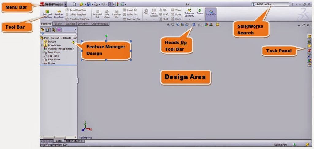
This is the visible image from the basic display of Solid Works before the software’s run. There are many kind of features which are served by Solid Works. Started from drawing part model then metal sheet and etc. In this software, we can also use engineering analysis such as a stressed analysis or fluid flow analysis.
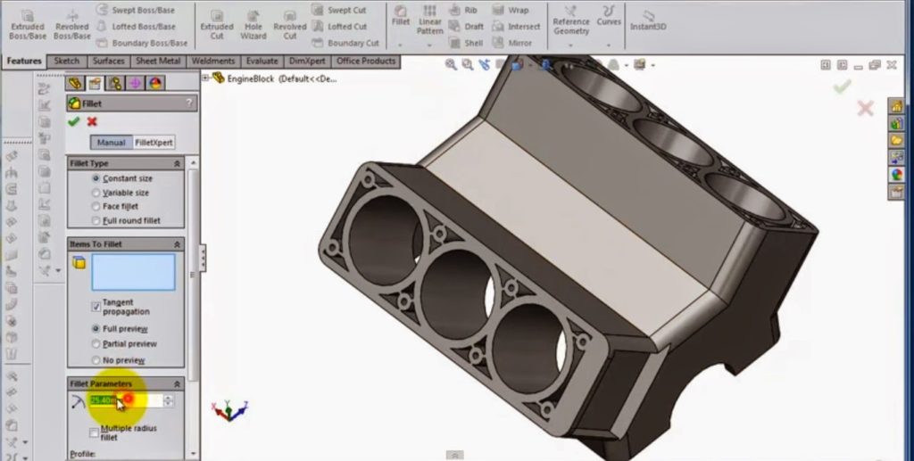
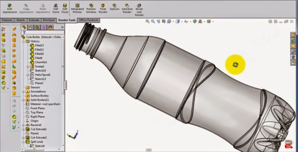
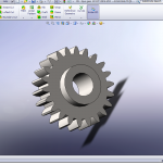
The Examples of SolidWorks Delineation Result


The Kinds of SolidWorks Tool Bar
 Line
Line
is a tool for making a straight line or angular on sketch image.
 Rectangle
is a tool for making a square line on sketch image.
 Circle
is a tool for making a circle on sketch image.
 Arc
Arc
is a tool for making a curve line or arc on sketch image.
 Polygon
is a tool for making a square that has 3 or 4 or 5 sides and so on on sketch image.
 Straight Slot
- is a tool for making a slot (a shape that has 2 circle centers that’re related each others) on sketch image.
 Text
Text
is a tool for making a text on sketch image.
 Extruded
is a tool for making a thickness for 3D model.
 Revolve Cut
is a tool for cutting model by rotating on 3D model.
 Revolve
is a tool for making a model by rotating sketch ‘till becomes a 3D model.
Resolve
 Swept
Swept
is to make a model based on the sketch by following swept sketch.
 Extruded Cut
is a tool for cutting 3D model by extrude methode.
 Hole
Hole
a tool for making a hole or threaded hole.
Thanks for read my article about the introduction of Solidworks, solidworks tutorial basic. After this you can try to go the next tutorial of solidworks. You can try make a part in Solidworks for first time.
More from my site
 How to Create Spur Gear in Solidworks 2019 – Solidworks Tutorial
 Design Spur Gear in Solidworks Manually – Solidworks Tutorial
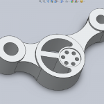 Let’s Design Control Arm With Solidworks – Solidworks Tutorial
 The Tutorial of Drawing Rod Cover with SolidWorks – Solidworks Tutorial
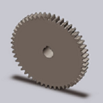 How to Make Spur Gear With SolidWorks – Solidworks Tutorial
 How to Make Rod Cover by SolidWorks – Solidworks Tutorial


