
Mastering one of design software is a must for current design engineers. It’s even better to master more than one of software design. Because in general the company will find employees as engineers who master software design such as Autocad, Mechanical desktop, Autodesk Inventor, Solidworks, Catia, Pro-e and others. Therefore, if we have aspirations to become an engineer, we must master one of these software. Here I will try to show how to design control arm with Solidworks, which I have previously tried to design control arm with Autocad.
Design Control Arm With Solidworks – Solidworks Tutorial
– First, open Solidworks, then click File, then select New or control N, and select Part.

– Select Sketch Menu and then click sketch

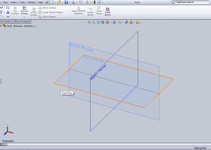
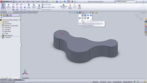
– Click Top Plane
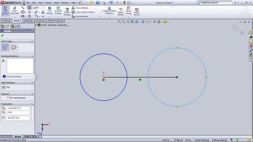
– Select circle menu, click center axis in area drawing and move a bit and click 1 time. Select line menu, click center axis in area drawing and move cursor so that make horizontal line and click again (we don’t give size to line or circle cos if we use solidworks, we will give the size after we make circle or line, different with autocad method. Check the video tutorial below to know more about this)
– Click circle again and click the end of line that have just made and move a bit until you make circle.
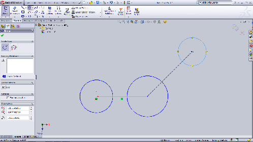
– Then we make a slash upward, click line menu, click center second circle and slide the cursor up so that it looks like this,

– Click line menu and then click the end of second line, move a bit until we make circle.
NEXT STEP
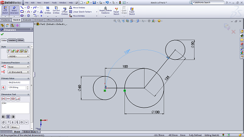
– We will give size or dimension to all of object. Click smart dimension menu, and click first circle and move to outside circle and click 2 times and type the dimension 60 mm (diameter) then enter.

– Give dimension to other object again. Click smart dimension and select first line and move a bit then click 2 times, type the size is 100 mm.

– Next, please give dimension to all of object. Second circle, the diameter is 100 mm. Third circle, the diameter 50 mm, and the size of second line is 125 mm and then the angle is 129. To give dimension of angle, the first you select smart dimension menu then click second line then click first line and move the cursor up and click 2 times, type 129 and click the green check or enter.
– Now we will use Arc menu. Click arc menu choose arc with 3 point, select first circle and select second circle and move outside circle and enter.

– Give dimension to arc object, the radius is 40 mm. Select smart dimension, click arc and move up then click 2 times, type 40 then enter. Still using smart dimension, click arc then click first circle and click arc, move cursor up, click 2 times, type the size is 34 then enter. Select arc again then select first circle and move cursor left and type 2 times, type 61.15 then enter.

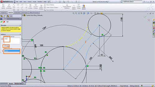
– Next, mirror the arc with mirror about the line that the size 100 mm. Select mirror menu, click the arc then click the line and enter or check the green check.

– Make arc again. Click arc menu choose arc with 3 point, select second circle and select third circle and move up a bit then enter.

Continue to Design Control Arm With Solidworks – Solidworks Tutorial
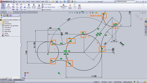
– Now we will give dimension to arc object. Select smart dimension, click arc and move up then click 2 times, type 60 and enter. Still using smart dimension, click arc then click second circle and click beginning of arc line and move right, click 2 times, type the size is 7.25 then enter. Select arc again then select end of arc line and move cursor down and type 2 times, type 10 then enter. (Make all lines black, it means locked and you can not move the line or arc)

– Next, we will mirror the arc that we have just made. Select mirror menu, click the arc then click center line of second circle and third circle that will use to be mirror about.
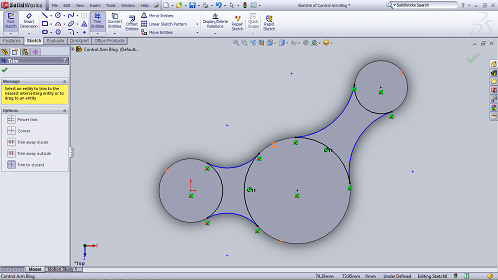
– Now we will trim all lines and arc that’s not used. Select trim and click all lines and arc that you want.

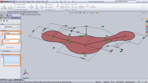
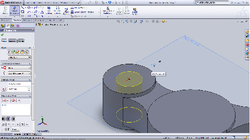
– Next step, we will extrude the sketch. Select FEATURES => EXTRUDED BOSS/BASE

– Fill all of parameters for extruded. Choose Mid Plane cos we want to extrude 2 directions (up and down), type the size is 50 mm, select the object in area drawing and enter.

– Then select Sketch menu and click top area object.
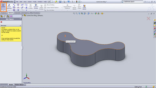
– Click top view
– Make arc and circle that follow all circles and arc that have just extruded.

– And trim all arcs that’s not used. See the result is like below:
– Select Isometric view, select Features – Extruded Cut. Select the area that we will extruded cut, type the size 5 mm, and make sure the arrow is downward in area drawing.

Continue to Design Control Arm With Solidworks – Solidworks Tutorial
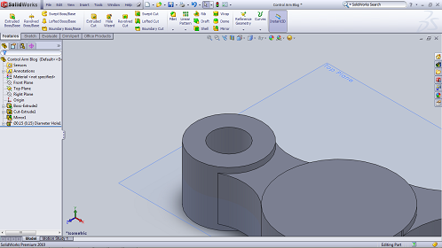
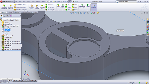
– Now we will extrude cut again but we will use mirror part. But before we extruded cut, we have to show the TOP PLANE this part. See the picture below:

– Next, select cut extruded that have just made and click mirror part.

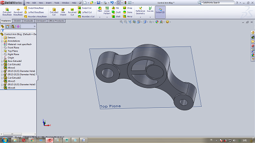
– Select top plane then enter or click green check.

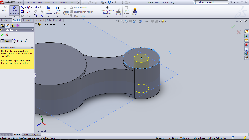
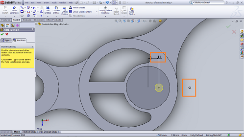
– Next step, we will make hole using Hole Wizard. Select hole wizard, and fill the parameters.

– In the positions menu, click top area of first circle. Give dimension with select smart dimension, then select first circle then click center of hole.

– Move a bit and fill the size is 0. And give the dimension to other side with size 0 then enter or check the green check 2 times.
– Make hole again in third circle. Select hole wizard, fill the parameters below:

– Select positions to place the hole and make dimension. Give the dimension 0 to X and Y.

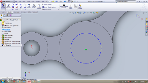
– Click Zoom to Fit menu then select sketch menu, click top of second circle. Active Top view.

 – Select zoom to area menu then zoom second circle / big circle.


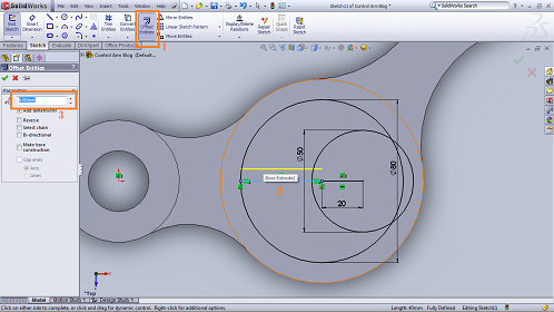
– Select circle menu and then click center second circle and move a bit and enter again.
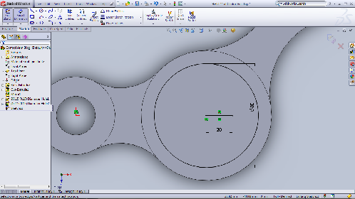
– Give dimension, select smart dimension, click the circle and move right or left the cursor and click 2 times, type the dimension is 80 and enter.

– Make line from center point of circle, select line menu and then click center circle then move right and click again. Give dimension 20 mm.
Next of Design Control Arm With Solidworks – Solidworks Tutorial
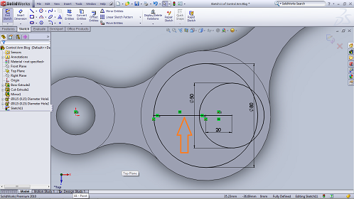
– Make circle again with center point is the end of line that have just made. And give the dimension 50 mm (diameter)

– Make line from center point of second circle or big circle to left quadrant. See the picture below.
– Now we will use offset menu to offset the line that we have just made. Select offset entities menu, click the line, fill the dimension 6 and enter or check the green check.
– Trim all lines that’ not used. Select trim entities, then select trim to closest, then click the line that you want to trim.


– Delete all line that is not used until like below:

Next of Design Control Arm With Solidworks – Solidworks Tutorial
– Give dimension the object with smart dimension.

– Click zoom to area, zoom the cone. Select arc menu and make arc. See the picture below:

– Give dimension the arc with radius 5 mm.

– Trim all lines that is not used until like below:

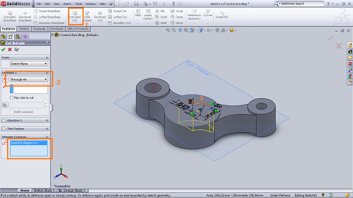
– Now we will extruded cut with the sketch that have just made. Before you begin to extruded cut, click isometric view first. Select extruded cut menu, choose through all, select the sketch then enter.

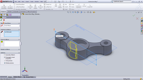
– Show the front plane, cos we will mirror the extruded cut. After that select cut-extrude2 in feature manager, then click mirror menu.


– Select the front plane and then enter or check the green check.

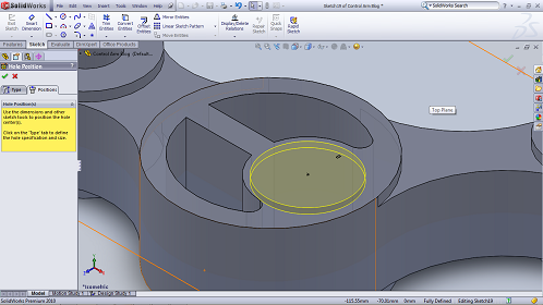
– Hide front plane. Now we will make hole in the second circle. Select hole wizard menu, and fill the parameters,

– Select positions menu then click top of second circle, and give dimension 0 cos we want to place the circle in the center of circle radius 25 mm, then enter. Check the picture below:
– Mirror the hole 3 mm with top plane as mirror face. Select hole 3 in feature manager, then click mirror, and select top plane then enter.

– Click top view and hide top plane. Make hole gain, with diameter 8 mm and through all. follow this picture.

– Select positions menu, and then click top of circle radius 22 mm.

– Select smart dimension and give dimension and then enter, see the picture:
– Now we will use circular pattern to copy the hole become 6 hole. Select Hole4 in feature manager, choose circular pattern,

– Fill the parameters, click the circle diameter 44 mm then enter, see the picture below:


– For finishing, you can do chamfer to the angle side that need it. Select chamfer then fill the parameters and choose the line or angle side.

– If you want to give material to this part you can select Appearances menu, select metal that you want.


That’s all and thanks for coming to my blog. Please share this article and follow my fans page facebook so that you can get the updated tutorial from me. And if you are still confused about this tutorial please come to my video tutorial in Youtube, also don’t forget subscribe my Youtube Channel.
More from my site
 How to Create Spur Gear in Solidworks 2019 – Solidworks Tutorial
 Design Spur Gear in Solidworks Manually – Solidworks Tutorial
 The Tutorial of Drawing Rod Cover with SolidWorks – Solidworks Tutorial
 How to Make Spur Gear With SolidWorks – Solidworks Tutorial
 How to Make Rod Cover by SolidWorks – Solidworks Tutorial
 The Introduction of Solidworks – Solidworks Tutorial Basic


[…] tutorial basic. After this you can try to go the next tutorial of solidworks. You can try make a part in Solidworks for first […]