
For this time, I would like to make an article about “How to make a gear with SolidWorks software”. Now, I will make a spur gear like in the image above that having 50 number of teeth. Making gear on SolidWorks are easier than making gear on Autocad because we just need to put the parameter likes Pitch Diameter, Modul, Shaft Diameter, and etc. Let’s begin to Make Spur Gear With SolidWorks.
How to Make Spur Gear With SolidWorks – Solidworks Tutorial
 |
| Design Library |
 |
| ToolBox |
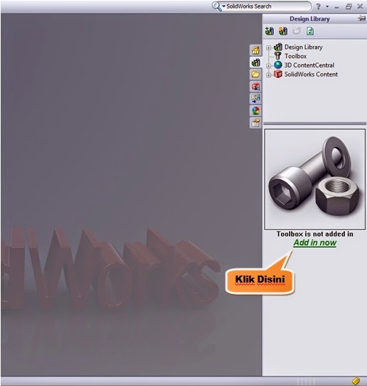
The first step is to click the Design Library then choose the ToolBox and then click Add-In Now. Look at the picture below :
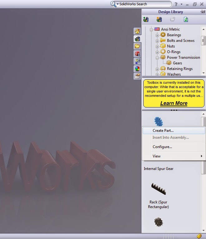
And then choose the ANSI Metric and click it twice.

Then choose and click the Power Transmission twice.

Then choose and click the Gear twice. After that, the kind of gear choices will appear. Then click the Spur Gear and click the right side of the mouse then click Create Part.
After that, there will be the choices of Feature Manager on the left screen sides. Then just put the parameter for gear that you’ll make.

On the image above we can see that the several gear parameter choices should be fill, and for this section, we will make a Spur gear that having a parameter like this:
- Module: 4
- Number of Teeth: 50
- Face Width: 20
- Hub Style: One Side
- Hub Diameter: 69
- Overall Lenght : 12,7
- Nominal Shaft Diameter: 30
- Keyway : Rectangular 1
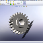
And after we’ve been fulfilled the parameter click the green checklist and the SolidWorks will running to process our gear design. Here we go, our gear would be like this.


Those are How to create Spur Gear with SolidWorks and if you want to modify the gear back, it means giving tapped hole to the keyway, just modify itself with your own design.
Just see the next tutorial.
More from my site
 How to Create Spur Gear in Solidworks 2019 – Solidworks Tutorial
 Design Spur Gear in Solidworks Manually – Solidworks Tutorial
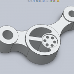 Let’s Design Control Arm With Solidworks – Solidworks Tutorial
 The Tutorial of Drawing Rod Cover with SolidWorks – Solidworks Tutorial
 How to Make Rod Cover by SolidWorks – Solidworks Tutorial
 The Introduction of Solidworks – Solidworks Tutorial Basic


very nice submit, i definitely love this website, keep on it dgedfcbgdedb
[…] all the way to Design Spur Gear in Solidworks Manually – Solidworks Tutorial. If you want to design spur gear or other gear easily you can design with toolbox menu, just fill the parameters of gear. If you are […]