
Maybe there is one of you that haven’t know about what is SolidWorks before and what kind of this displays? Why in AutoCAD I didn’t see it. So, this is the New Document display from SolidWorks which is there are choices are served here. Let’s begin to Make Rod Cover by SolidWorks – Solidworks Tutorial
 |
| “New” |
Click New Menu for beginning the new drawing or you can open new tools from the FILE Menu, then click New. And after that, suddenly there will be the displays like this.
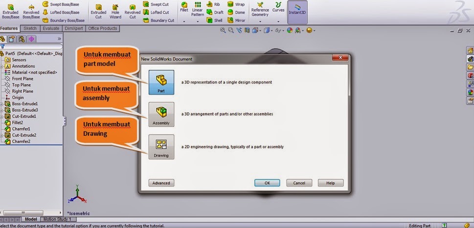
1. Part: This menu is for drawing a part, some machine or another thing like scissors. A scissors itself are consists of the top handles, handles down, top blade, bottom blade, and screw. If we try to take part one by one of that scissors maybe there will be 5 part that contained on scissors. On every part will be drawn from a different page and it will be combined in an assembly page of the SolidWorks. And I’ll explain in my next article that explaining about The Way of Making Assembly by SolidWorks or How to assembly part by SolidWorks.
2. Assembly: assembly is combining 2 part or much more being the shapes that we want.
3. Drawing: Drawing is a page for drawing 2D from a part or from the assembly that we’ve been made. The purpose itself is to present our design.
How to Make Rod Cover by SolidWorks – Solidworks Tutorial
Because of we wanna drawing apart so that, just click part on the New SolidWorks Document. After that, there will be the empty display like this.

For make it easier, click the View Orientation and choose the front view. See this below image.
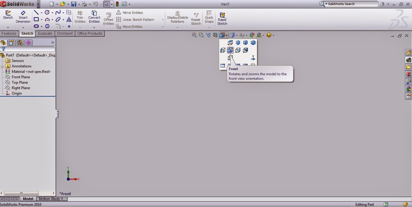

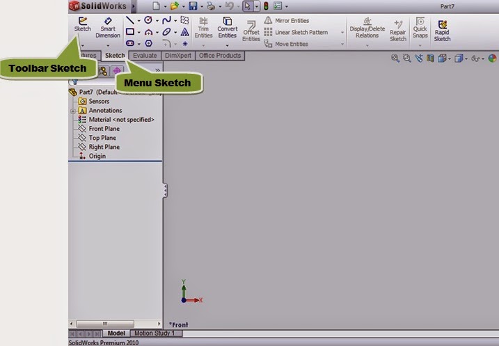
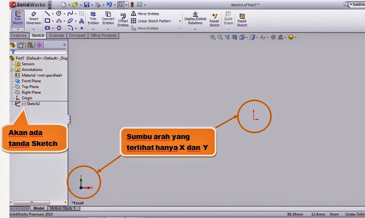
For seeing the axis, if the axis only looks like x and y so it is true. Like the image above. And after that Click the Sketch Menu and click sketch Toolbar. See this below images :
Then the display would be like this below.
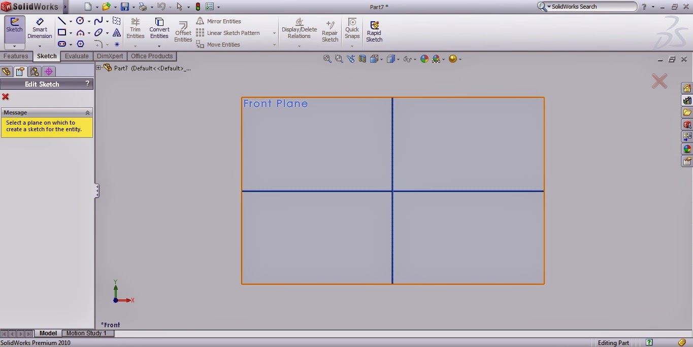
- After the displays of front plane appear, drag your cursor to the center screen or the design space, until the front plane line getting yellow like in an image above then click it. When you finish of choosing your sketch with a front plane. And the displays would be like this.

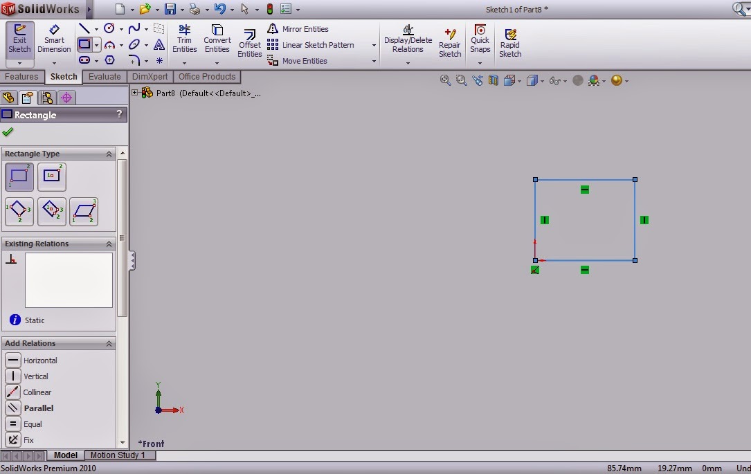
Click Rectangle on the Toolbar. Then click in the middle of the screen or in the 0 XY axis point. Drag it to the right and click once. Then the display will be like this.

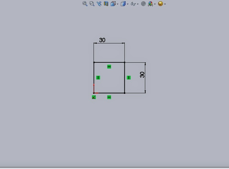
Click the Smart Dimension Menu on the Toolbar. Click the which one line of the square that you’ve been made then drag it to aside and click it once. Then input the size, the size is 30 (30 mm), then click the green checklist. After that, back to the other line then drag it to aside, click it once and put the size again type 30 (30 mm) then click the green checklist. So, the display would be like this.

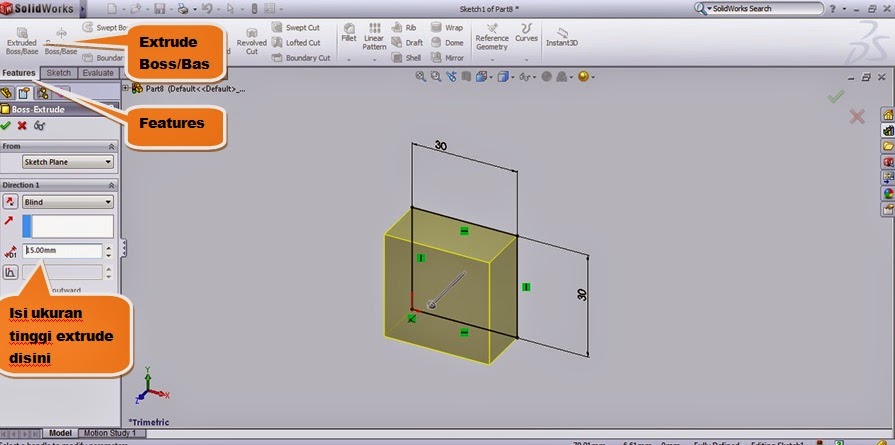
Click Features and Extrude Boss/Base. Fill the high extrude size like in this below image. Then click the green checklist under the features.

Then the result would be like this. Click the Zoom to fit (the position is in the up of the screen and under the toolbar).

The next step is, click the sketch then sliding the cursor to the front center of a part till the front line being yellow then click it once. Look this image.
 |
And here is the result.

 |
| “Cyrcle” |
Click the circle on the Toolbar. Then sliding the cursor to the middle of the front part, the sketch places that we’ve just made. Click it once then drag the cursor to the aside. Click it once by dragging the cursor don’t drag it to the width. After seeing this below image, click the green checklist under of the feature manager.
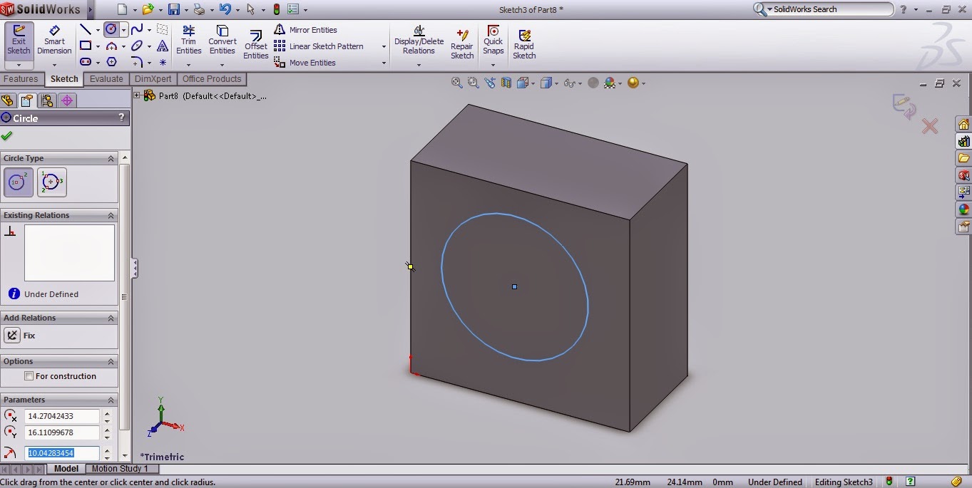
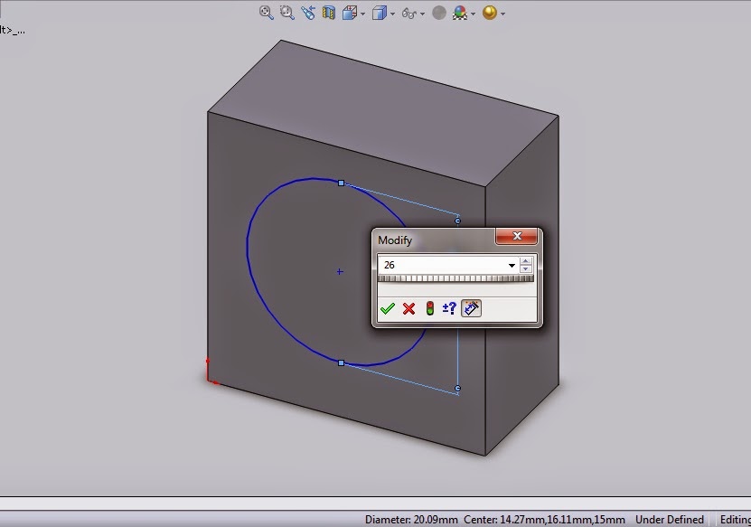
Click the Smart Dimension on a Toolbar. Click the Circle sketch that we’ve just made. Sliding the cursor to the aside and click it once. Input the size for the diameter of Circle 26 mm, then click the green checklist. Look this image.
Next, we drag the Circle sketch to the middle by click the line of the Circle or click the point of Circle center. Click the front side line (Line 1) then fill 15 (15 mm) and click the line of the Circle or the the point of Circle center. Look this below image.
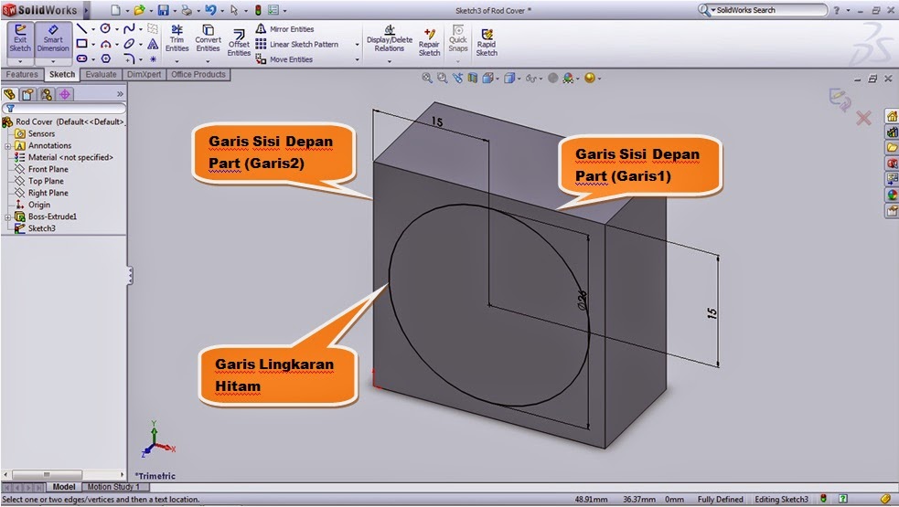
If the line of circle are having black color and the size’s color are black it means true. The black’s line of the Circle means that the sketch is blocked and couldn’t be edited anymore.
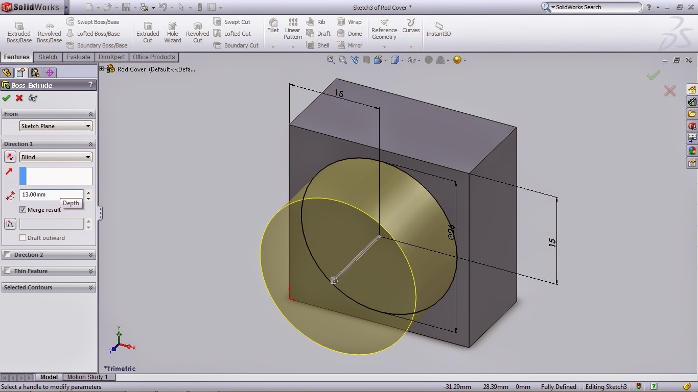
Click Features then click Extrude Boss/Base. Then input Depth Extrude size 13 (13 mm), then click the green checklist. Look this bellow image and look at the instruction to fill the parameter extrude on Design Features Manager.
Click sketch again then sliding the cursor in front of the part, in the middle of the Circle that we’ve just extrude before, then a line of the Circles being yellow then click it once. Look at this image.
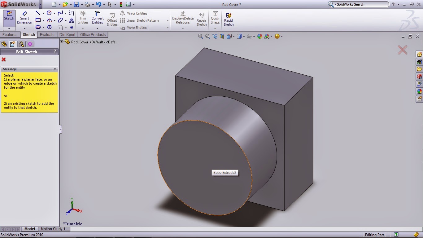
And the result would be like this :

|
| “Cyrcle” |
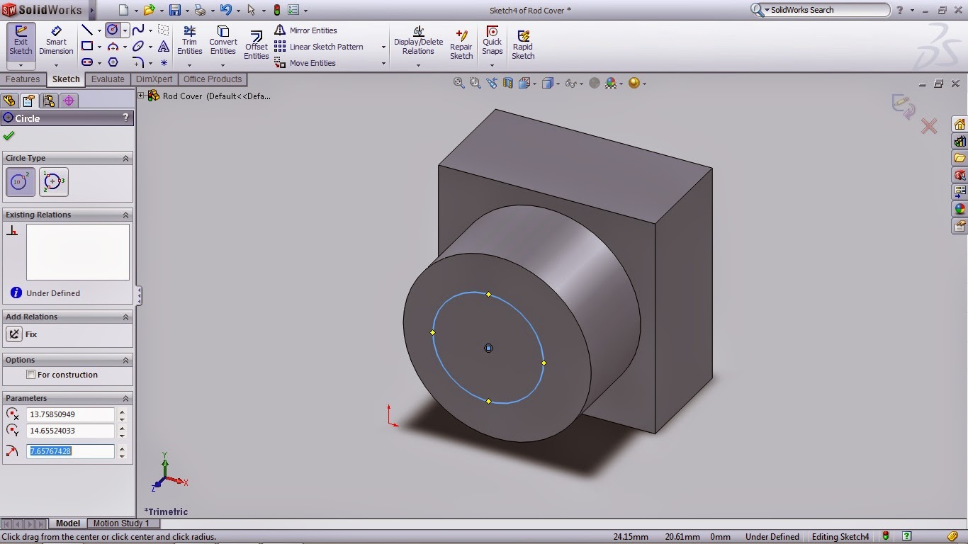
Then click the Circle on the toolbar menu. Then sliding the cursor to the middle sketch that we’ve just made or sliding to the point of sketch center then click it once, after that drag to aside and click it once (for make it easier to give a size don’t let the Circle exceed the things). Look this image.
After that, give the size to the Circle then click Smart Dimension. Then click the Circle that we’ve just made and click the line of Circle in the front part side. (Line 1). Look at the image.
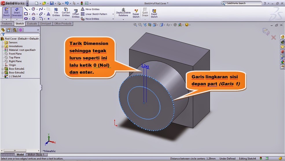
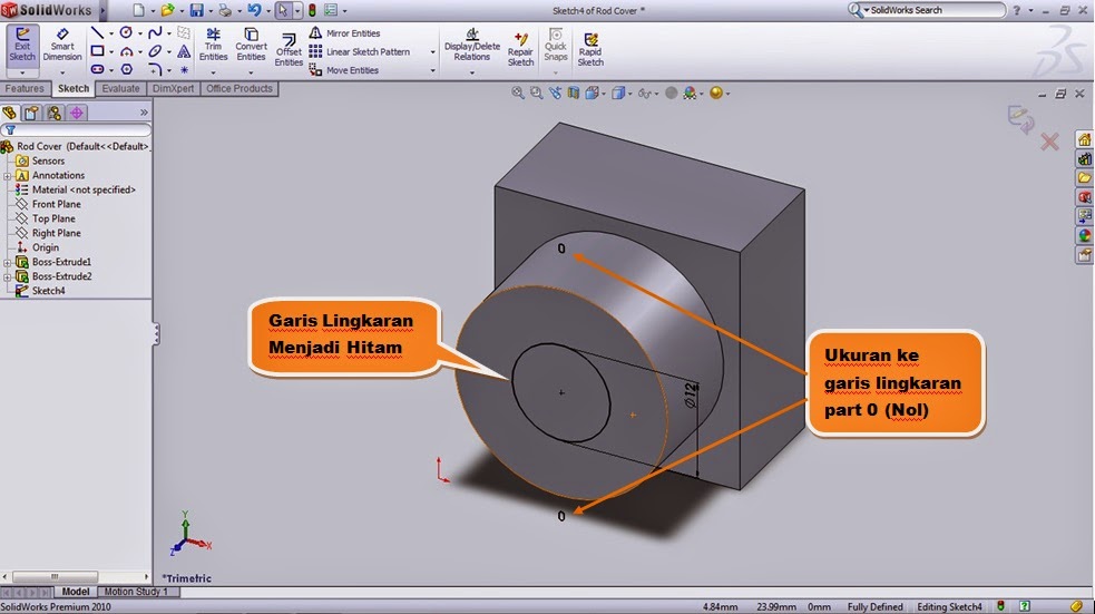
Sliding the perpendicular Circle dimension like in the image above, click it once then input the 0 size. The purpose is in order that the Circle are fit in the 0 point. Then give the size to the next side by clicking the Circle again and click the Circle line part side (Line 1). And sliding the perpendicular cursor to the X axis aside. Look the image.
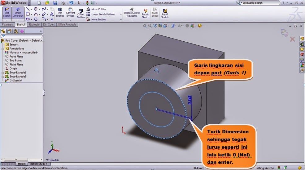
After that, click it one and input 0 (zero) sizes then enter. Give the Circle a size by clicking the circle then drag the cursor, click it once and input the size 12 (12 mm). Look this below image.

Then click Extrude Cut Menu. Choose the parameter that you want. Look this below image.
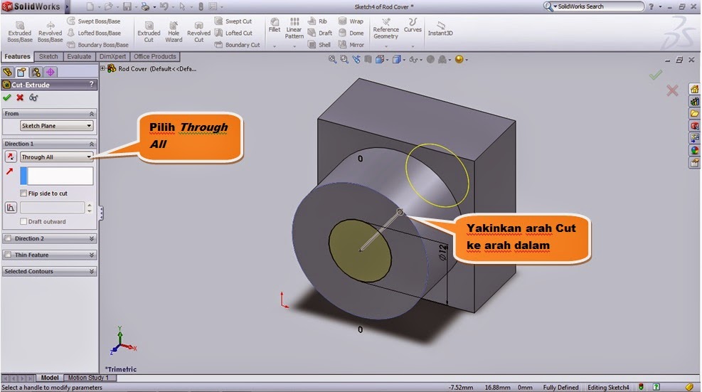
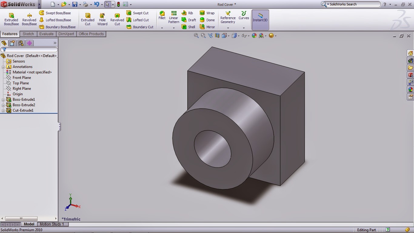
After that, click the green checklist on a design features manager. And here is the result.
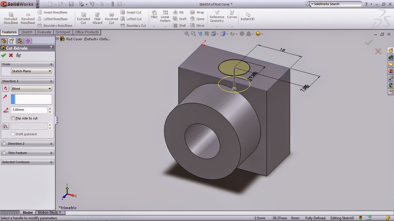
The next step is, make a hole on the up box that we’ve been made on the sketch 1.
Here is the way:
Click the sketch on toolbar menu. Sliding the cursor to the up box then the line looks yellow then click it once. Look at this image.

Here is the result.

|
| “Cyrcle” |
Click the Circle on a Toolbar. Then sliding the cursor to the middle of the sketch that we’ve been made, then click it once. Drag it to the Circle aside then click it once. Look this below image.

Click Smart Dimension. Then click the Circle and input the size 9.5 (9,5 mm), then enter or click the green checklist. Give the size on a sideline of the square side. If you still in Smart Dimension menu you just need to click the Circle that we’ve just made, click the length from the part of the square then drag it to aside and input the point. Like this, length : 2 = 15 (30 : 2 = 15 mm). Then enter.
Give the size on the other side, click the Circle then click the width line side and click it once. Give the size that is width : 2 (15:2 = 7.5 mm) then enter or click the green checklist. Look this below image.

Click Features and click Extrude Cut. Fill the size 5.8 (5,8 mm) on a Design Features Manager. Then click the green checklist.
And the result would be like this.

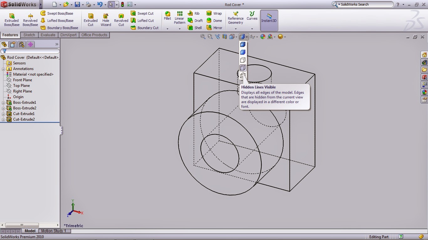
Next, we’re gonna use Fillet menu to fillet the box side’s square. But before it, we need to reveal the model part to be hidden, by clicking:

Click Hidden Lines Visible till the part looks hide and just looks the line. Look at this image.

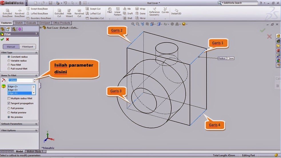
After we click the Fillet menu on a Toolbar. Choose the line that gonna be fillet and fill the size like what you want on a Features Manager. Then click the green checklist.

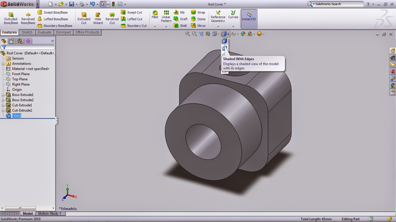
For seeing the real result just click Shaded With Edges. Then the displays would be like this.
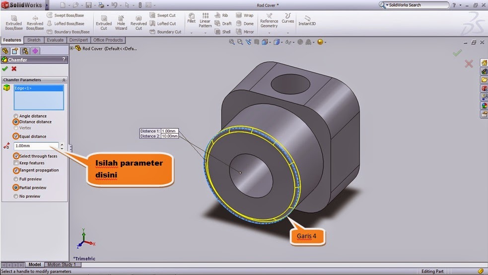
Click Chamfer Menu on a Toolbar. If you’re confused to looking for the toolbar, just click a little arrow under the fillet icon, then you’ll see Chamfer menu. If you’ve been click Chamfer, then click the line that you’ll chamfer and fill the size 1 (1mm). Look this image.
And here is the result of the Chamfer.

 Then click Chamfer again. Then click the hole sideline on a sketch 4. And fill the size 0.5 (0,5 mm) and choose the parameter and click the green checklist. Look this below image.
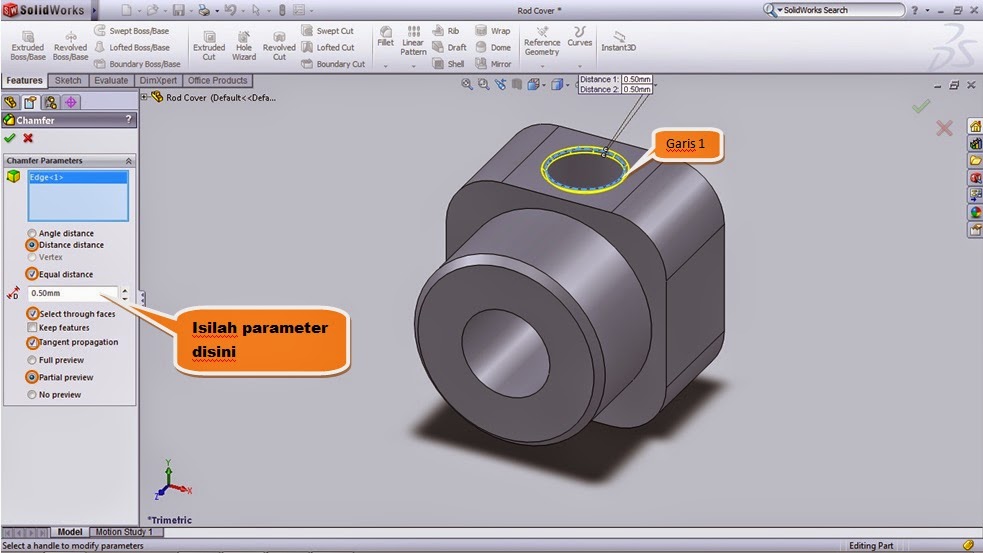
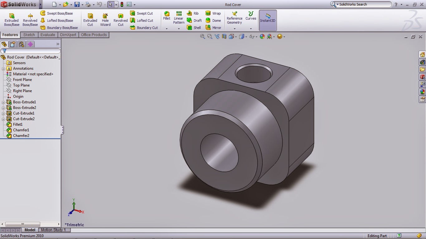
here is the result of the Chamfer. Look at the picture below :
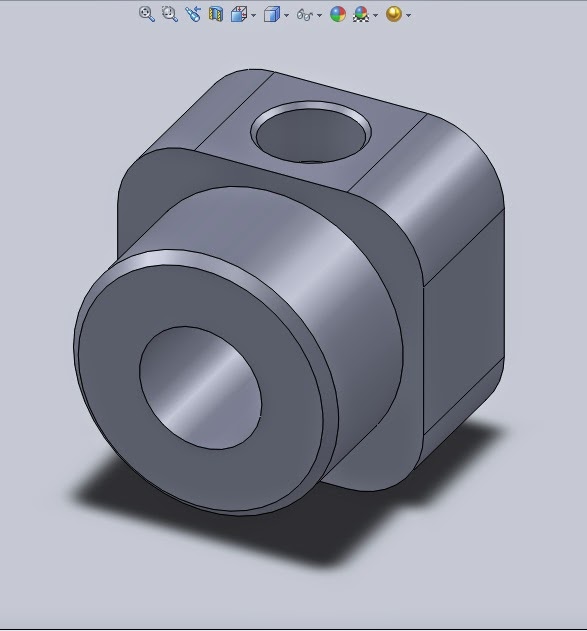
Here is the resulting image of Rod Cover design:
More from my site
 How to Create Spur Gear in Solidworks 2019 – Solidworks Tutorial
 Design Spur Gear in Solidworks Manually – Solidworks Tutorial
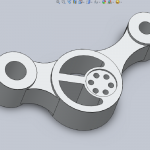 Let’s Design Control Arm With Solidworks – Solidworks Tutorial
 The Tutorial of Drawing Rod Cover with SolidWorks – Solidworks Tutorial
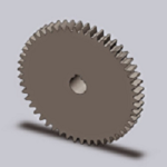 How to Make Spur Gear With SolidWorks – Solidworks Tutorial
 The Introduction of Solidworks – Solidworks Tutorial Basic


